3D printing settings
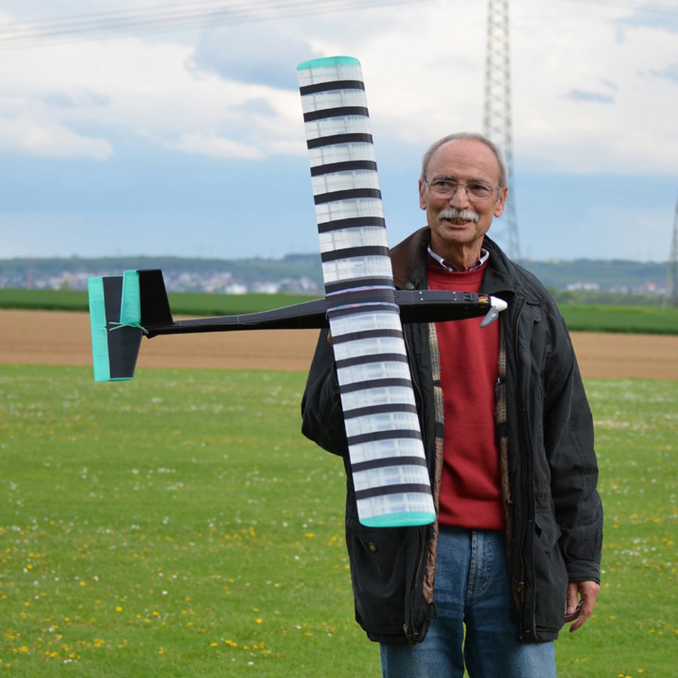
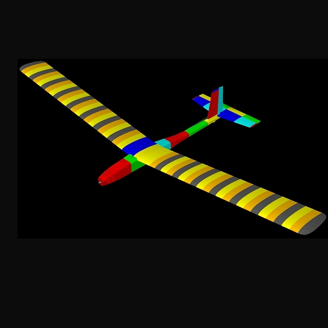
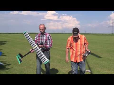
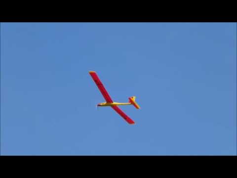
Yesterday we finally could start my radio controlled
motorised sailplane though the weather was very unsettled, partly raining and more wind then we wanted. But we wouldn't like to wait anymore.
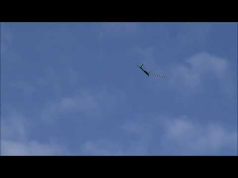
Everything went well until at the third base leg. It seemed that it bored it already. First the plane suddenly got rid of one wing and looked for a quick landing. It was the field strait below.
Well, this was what I was worry about. The 8 bend is a weak point because the carbon tubes are not going through, they only meet each other. The middle 8 wing sections were printed with 3% infill, 0.2 mm layer height and ratio: 1.2 = 0.24 width, just to save weight.
In the meantime I printed it with 4% infill, layer height 0,3 mm and ratio: 1.2 = 0.36 mm. At the meeting points of the tubes I set a 4 mm wall, so the holes are not going through anymore. This gives a stable impression and I think even less infill would do it. We are just waiting for better weather to test it.
Also the fuselage broke at the connection between the forth and fifth section due to the hard crash. This part is hollow printed only with one perimeter but strong enough to survive normal landings.
I glued it already with additional thin printed patches on top and bottom side.
It is very important to have these parts as light as possible. Otherwise it displaces the centroid dramatically backwards and you will need ballast in the front.
Due to the high off weight of almost 960 g it needs a powerful motor and naturally a big and heavy accu. Accordingly the plane has to fly pretty fast. That means more stress to the parts and bonding surfaces as well. PLA is not easy to glue.
I want to give thanks to members of the ACNE.
Fortunately we have a lo of experienced pilots at the Aeroclub Niedereschbach ACNA e.V. nearby Frankfurt Germany: http://aero-club-nieder-eschbach.de
Without them, the plane would not have left the ground yet.
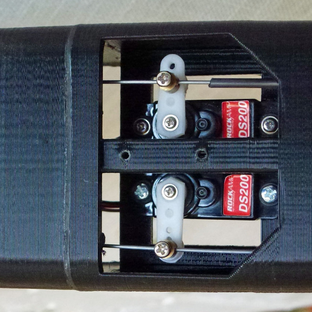
After I finished my design, I contacted them and they were so kind to give me valuable tips. So I had to redesign the whole fuselage other ten the tail. First I placed the servos one behind the other and planed to move the vertical rudder with two pull ropes. For more favourable centroid now they are side by side and moved more to the front. The steering is now controlled by 0,8 mm wires, which partly lie in 2 mm carbon pipes.
The holes in the rudder horns had to be smaller and are now 1 mm.
The centroid problem made it necessary to extend the nose extensive. To avoid ballast I tried out several noses. The current nose is now 55 mm longer and doesn't looks very good but needs no ballast anymore. To make it in harmony with the rest of the fuselage I have to redraw the complete fuselage. It will be a lot of work and I don't know, if I will find the time because I am already designing my next project reaching 2 meters wingspan or even more :-)
The plane became pretty heavy. The empty plane weights about 650 g. The wing (meanwhile 1550 mm wingspan) is the heaviest part: 450 g.
All together there are now nearly 960 g.
Wings
ATTENTION!
Before you are going to print the final wing, you have to buy the carbon rods and make sure that they fit into the wings because there are different!
I ordered some other (more light ones) and couldn't use them. If your rods don't fit, I will change the holes for you. If they are a little tight you can drill them carefully, or better use a reamer. The rods have to fit a bit tight so you don't need to glue. Glue makes it heavy.
I tried several ways to print the wings. The easiest and fastest way was to print only hollow 30 mm sections without infill and only one perimeter. Thus, all 30 mm results in a rib in each case consisting of 2 bottom layers and 2 top layers. If the holes in the wing sections are close-fitting enough you don't need to glue them. Just slide the wing panels onto the carbon pipes close together. The torsional stiffness will be good enough. But to hold the wings secured to the middle section tape them together with tape.
The two middle wing sections must be glue together of course.
This type of wing sections are up to 60 mm length suitable.
The most rigid type is the one with designed infill structure (wing_90_infill). You can print it as high as your printer can do. The only disadvantage is: it takes very much time.
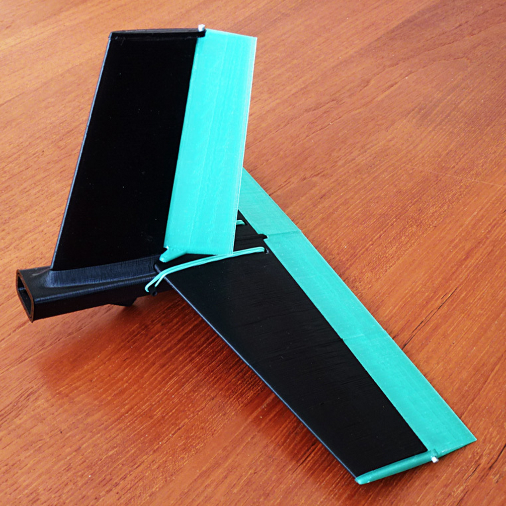
Fin
All fin parts have holes for to dowel them together. 2 mm for 1.75 filament and 3.2 mm for 3.0 mm filament. These are only for adjusting. Of course additional they must be glued.
The inner horizontal rudders and the fin rudder have support on underneath its mounts.
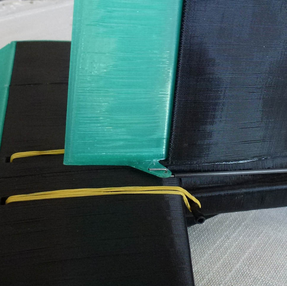
Before fitting the horizontal middle fins to the tail you must remove very accurately the jutting edge of the first layer. Especially the inner nooks of the vertical nose have to be file off carefully.
Then the horizontal fins will fit exactly and tight to the tail and you almost don't need rubber bands for fastening :-)
The tail and rudder parts I printed with 0.3 mm layer height, 1 perimeter, 2 solid layers on bottom and top and no infill.
The rudder mounts with 0.2 mm layer height, 3 perimeter and 50% infill.
The inner ring on one side of each fusselage part is also a support. These must carefully break off or cut off afterwards.
All parts of the fusselage are printed with layer height 0.3 mm, 1 perimeter, 2 solid layers on bottom and top and no infill.
Except for the nose!
The motor frame is 2.5 mm thick and has to be solid. So you need at least 8 solid layers on bottom.
Edit 26.06.2013
I added new middle wing sections with structured infill. They are light and strong and already tested:
Wing_light_centerc._left_brim.stl
Wing_light_centerc._right_brim.stl
Edit 18.09.2016
I added a larger rudder for the fin "fin_rudder large".
I warmly recommend it because it increases the flight stability.
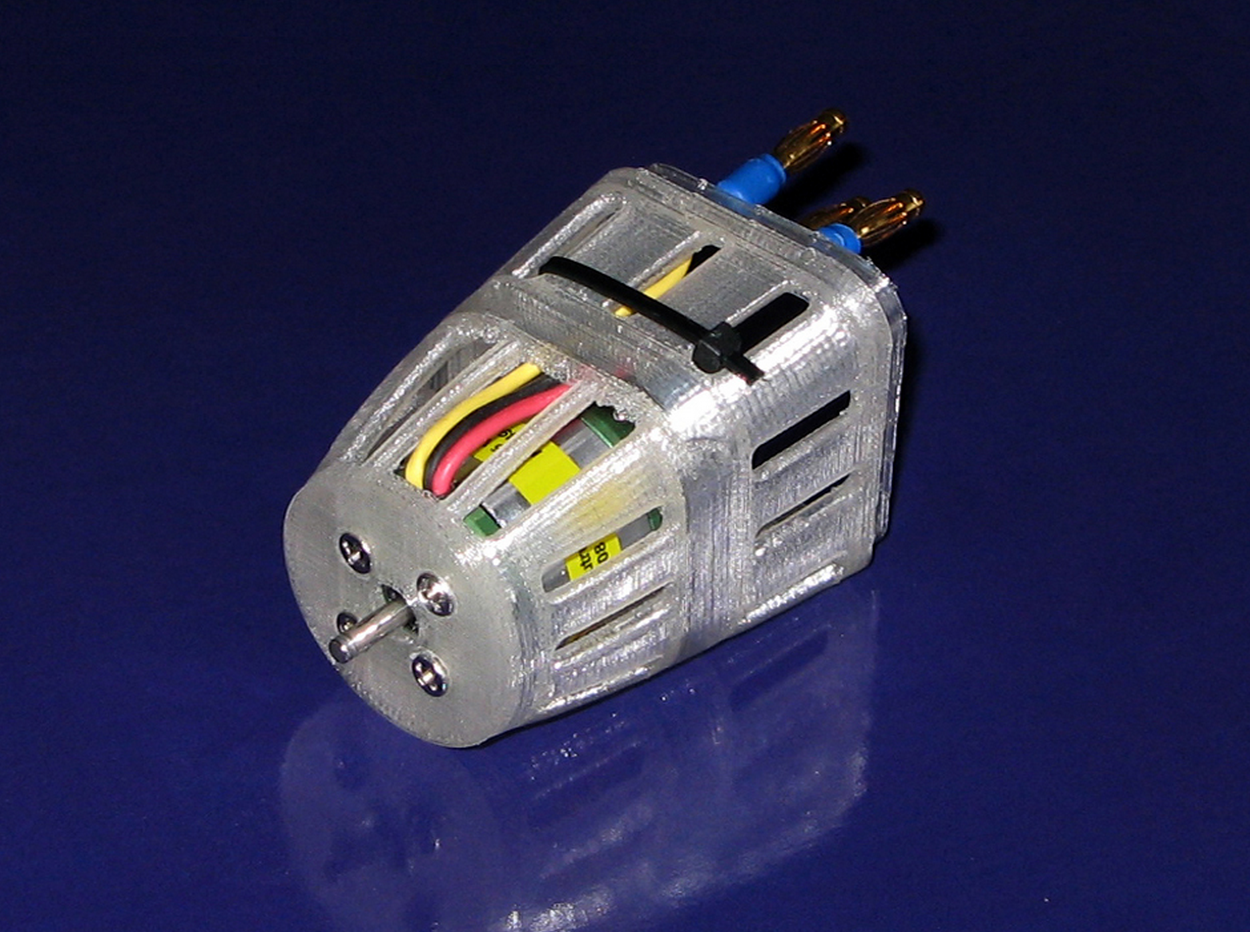
Motor
Roxxy BL-Outrunner 2834/08
http://www.robbe.de/catalog/product/view/id/1282/s/roxxy-bl-outrunner-2834-08/Regulator
Batterie
Propeller
Aeronaut Carbon Classic 9 x 6.5" / 23 x 16.5 mm
shop.modellbau-freudenthaler.at/index.php?list=86
Propeller Mount
Axis-center distance: 45 mm
Borehole for motor shaft: 3.17 mm
Spinner
Outer diameter: 35 mm
Servo
ROCKAMP DS200
http://shop.kjk-modellbau.de/shop/cgi-bin/shop.dll?SESSIONID=0793802465545014&AnbieterID=27
Operating voltage: 4.8 V
Response time: 0.11 sec
Torque: 1.4 kg
Transmission: Carbonite ball bearings,
Weight: 9g
Dimensions: 23x12x24mm
Carbon Tubes
2x 8/6 mm (outer/inner diameter) x 740 mm long - (for the wings)
1x 8/6 mm (outer/inner diameter) x 59 mm long - (for the wing middle sections)
2x 4/3 mm (outer/inner diameter) x 729 mm long - (for the wings)
1x 4/3 mm (outer/inner diameter) x 59 mm long - (for the wing middle sections)
1x 4/3 mm (outer/inner diameter) x 74 mm long - (front holding-down rod for the wings)
1x 4/3 mm (outer/inner diameter) x 72 mm long - (back holding-down rod for the wings)
1x 4/3 mm (outer/inner diameter) x 47 mm long - (holding-down rodd for the horizontal fin)
1x 2/1 mm (outer/inner diameter) x 210 mm long - (for the vertical rudder)
1x 2/1 mm (outer/inner diameter) x 450 mm long - (for the horizontal rudder)
Wire
1x 0.8 x 520 mm long (for the vertical rudder)
1x 0.8 x 470 mm long (for the horizontal rudder)
The next days I will give more information.
:format(webp)/https://fbi.cults3d.com/uploaders/4244034/illustration-file/1439896397-14732-6423/Capture_d__cran_2015-08-18___13.08.47.png)


:format(webp)/https://fbi.cults3d.com/uploaders/4244034/illustration-file/1439898113-14732-3549/Capture_d__cran_2015-08-18___13.40.44.png)
:format(webp)/https://fbi.cults3d.com/uploaders/4244034/illustration-file/1439899315-14732-0445/Capture_d__cran_2015-08-18___14.00.15.png)
:format(webp)/https://fbi.cults3d.com/uploaders/4244034/illustration-file/1439899740-14732-5541/Capture_d__cran_2015-08-18___14.08.14.png)
:format(webp)/https://fbi.cults3d.com/uploaders/4244034/illustration-file/1439900086-14732-9764/Capture_d__cran_2015-08-18___14.12.09.png)
:format(webp)/https://fbi.cults3d.com/uploaders/4244034/illustration-file/1439900632-14732-6348/Capture_d__cran_2015-08-18___14.21.50.png)
:format(webp)/https://fbi.cults3d.com/uploaders/4244034/illustration-file/1439901430-14732-6693/Capture_d__cran_2015-08-18___14.34.19.png)
:format(webp)/https://fbi.cults3d.com/uploaders/4244034/illustration-file/1448113118-6906-1559/Capture_d__cran_2015-11-21___14.36.14.png)
:format(webp)/https://fbi.cults3d.com/uploaders/4244034/illustration-file/64d9a958-0b07-4fa0-a51f-299e67071c64/Capture%20d%E2%80%99e%CC%81cran%202017-09-25%20a%CC%80%2009.54.11.png)
