3D model description
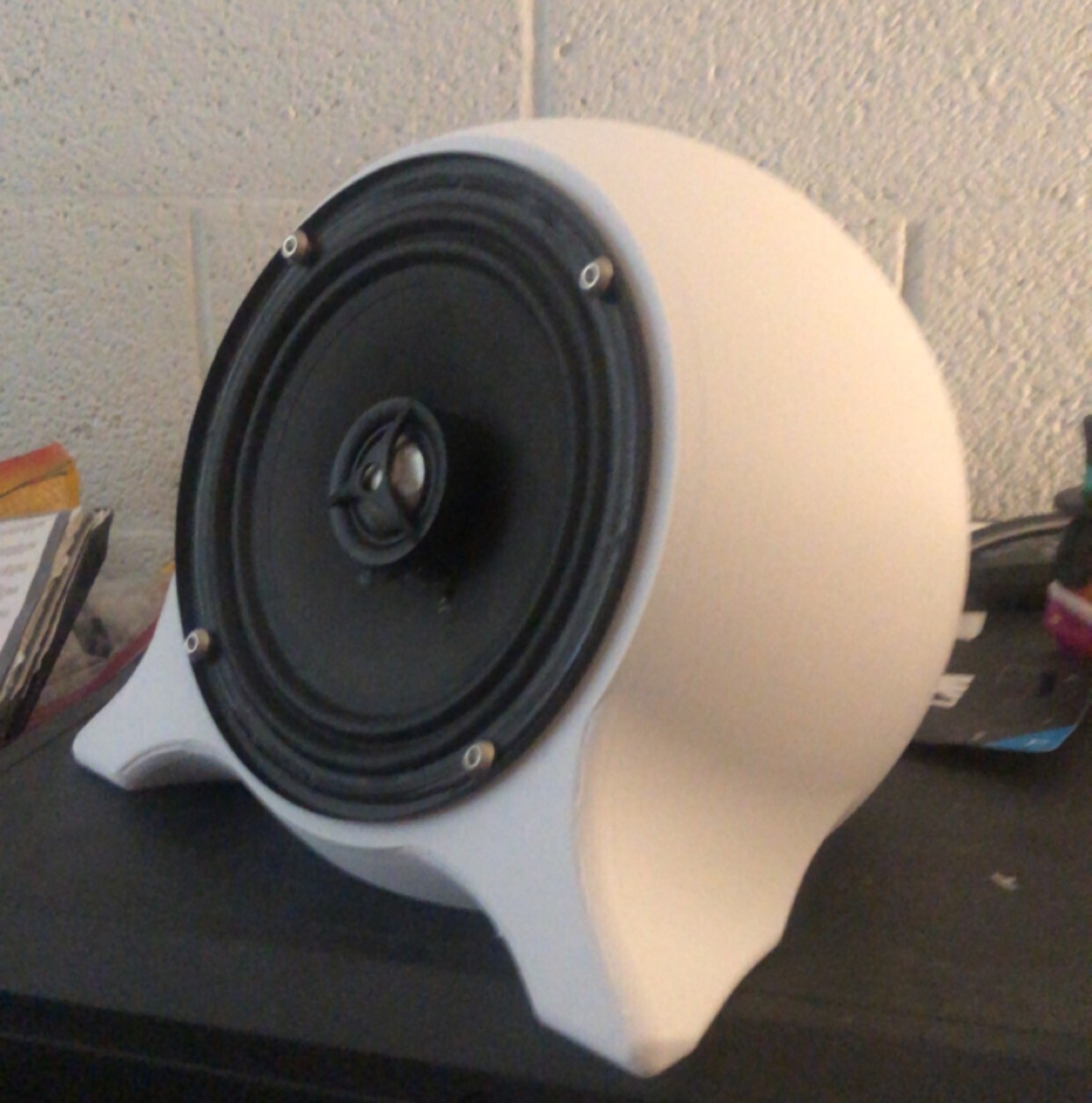
3D Printed Sphere Speaker Enclosure
This 3D printed sphere speaker enclosure is designed to accommodate 6.5-inch speakers. Before starting your build, ensure that the mounting hole spacing of your speakers is compatible with the design. The enclosure uses a 1/4" female jack for a cleaner wiring setup. If you opt to use these jacks, be sure to get speaker cables instead of instrument cables, as the latter are not designed to carry the necessary power for speakers.
The design also includes additional files needed to convert a 1/4" male jack to a spring terminal female. This conversion helps maintain a secure and efficient connection for your speakers if your amplifier does not have 1/4" female jacks as outputs.
Required Materials
Speaker Jacks
GLS Audio 1/4" Jacks Female TS Mono Panel Mount Jack - 20 Pack link
Spade Crimp Terminals
VONVOFF 30pcs 4.8mm Spade Crimp Terminal, Female Electrical Insulated Terminals with 20cm 16AWG Cable, Spade Quick Connectors with Insulating Sleeve, 30 Packs link
Speaker cables (these are the ones I used, but it seems like they are out of stock. look for similar language in the title)
Ignite Pro 2X 1/4" to 1/4" 25 Ft. True 12 Gauge Wire AWG DJ/Pro Audio Speaker Cable, Pair link
Mounting Hardware
- M4 or M5 Hardware: Required to attach the speaker to the 3D printed enclosure. The length of the hardware will depend on your specific speaker model. It is recommended to use washers with a nylon locking ring to prevent vibrations from loosening the screws.
- M3 Hardware: Needed to attach the speaker back to the enclosure. This includes M3 square nuts and 10mm M3 bolts, optional are lock washers to keep M3 bolts from backing out once installed.
- 3mm Drill Bit (or 1/8in Drill Bit): Required to drill out the holes which have a thin cover on them to assist with printing.
Assembly Instructions
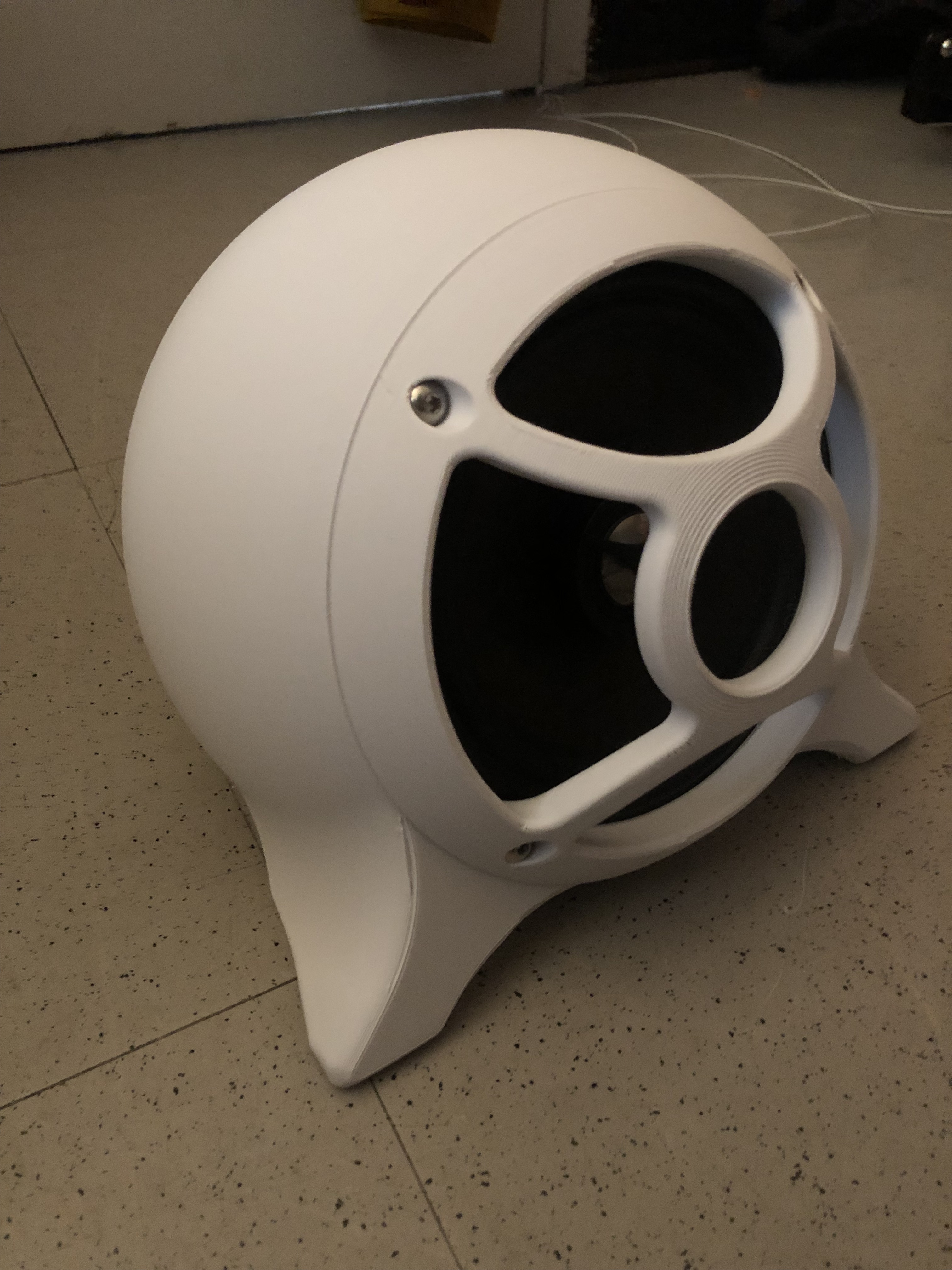
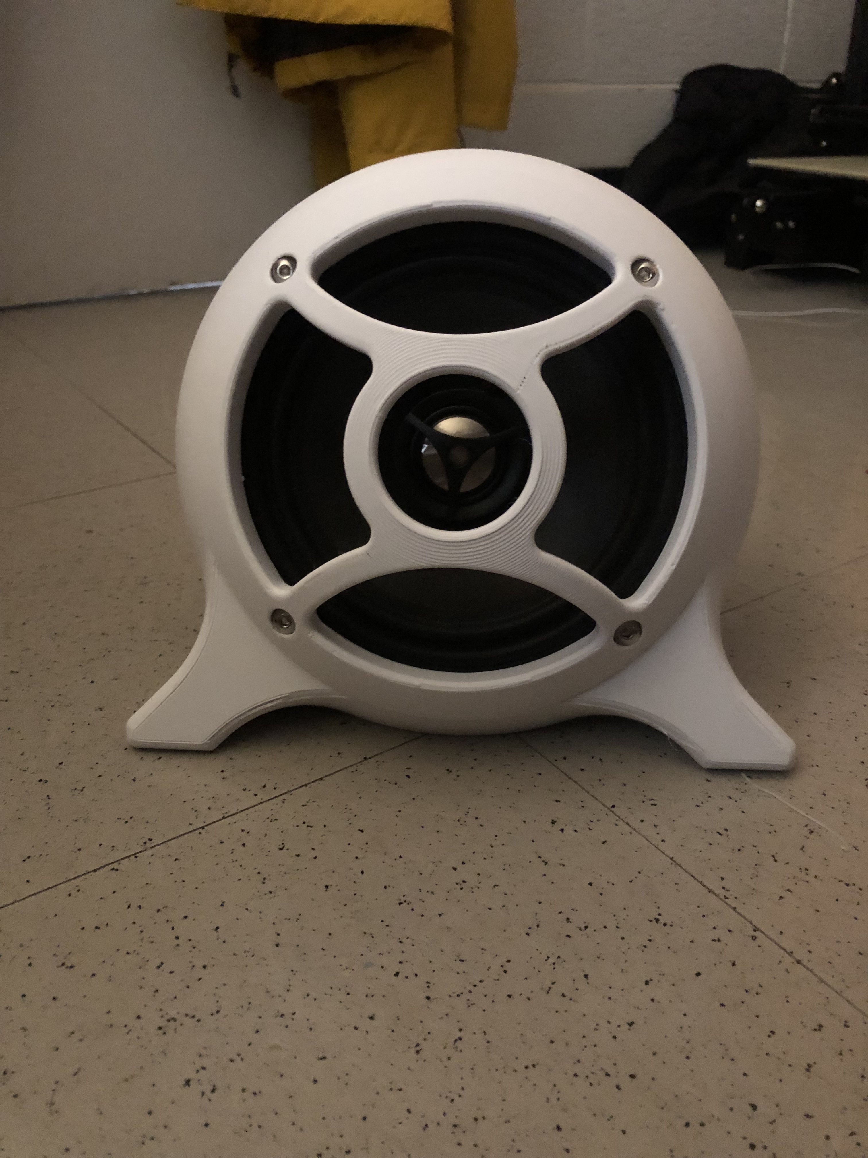
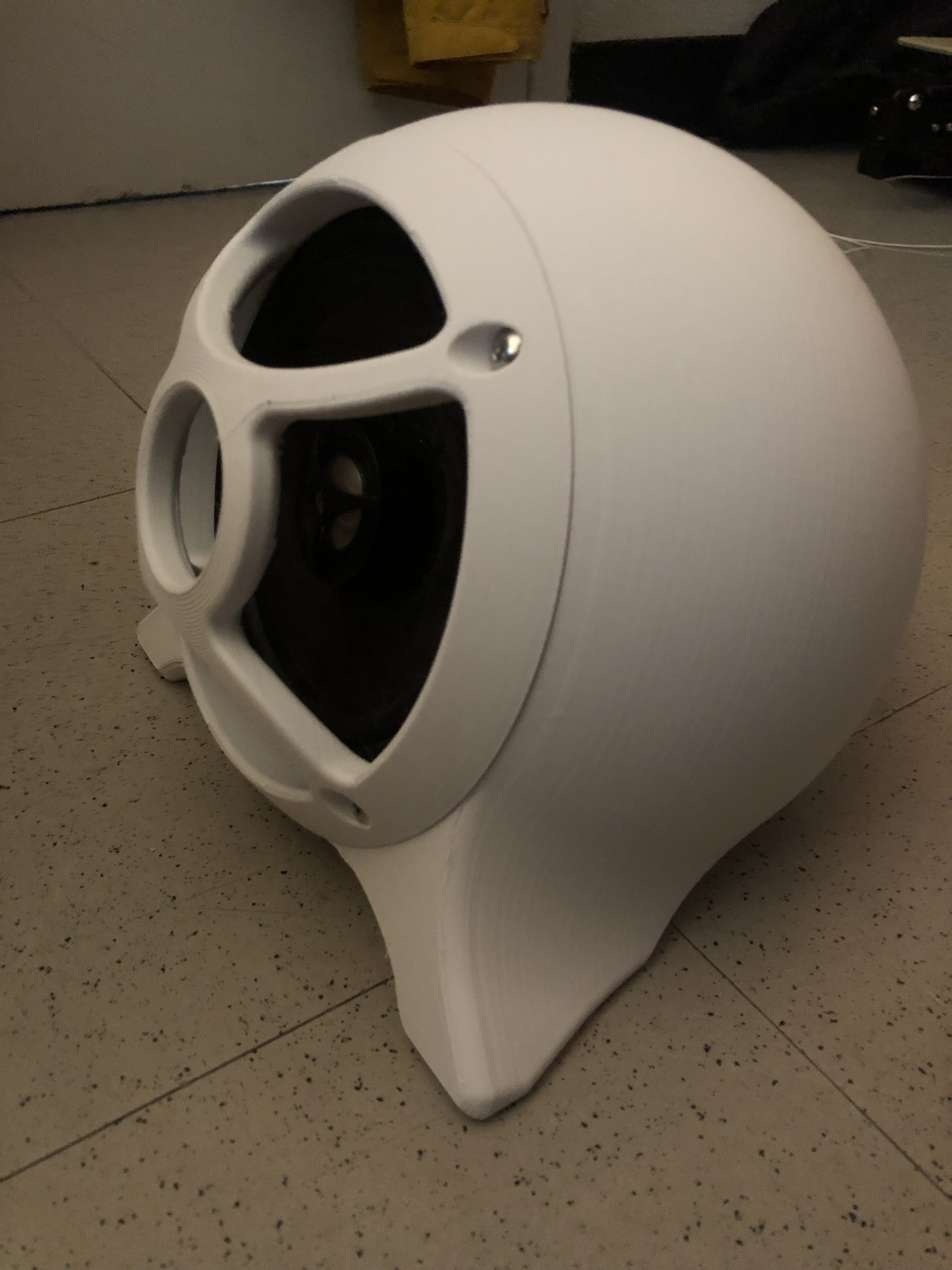
Print the Enclosure: Ensure your 3D printer is set up correctly to handle the specific dimensions and material of your chosen filament. I used PLA from ESUN but most any material should work. The speaker enclosure is designed to be printed without supports, however there are two versions of the speaker body, one is the normal body, which is designed to be printed on the speaker mounting surface and the experimental body which is printed on the backplate surface (see images below for pictures of printsetup, fig 1 and fig 2). The experimental body is for speakers that have a funky lip on their rims or a plastic bezel and you would like the speaker to be inset to use the included 3D printed grille. If your speakers come with their own grille and you wish to use it, the regular body will be your best bet as it uses much less material and your speakers may mount better.
Drill Mounting Holes: Use a 3mm (or 1/8in) drill bit to open up the thin covers over the mounting holes on the enclosure where the back plate goes
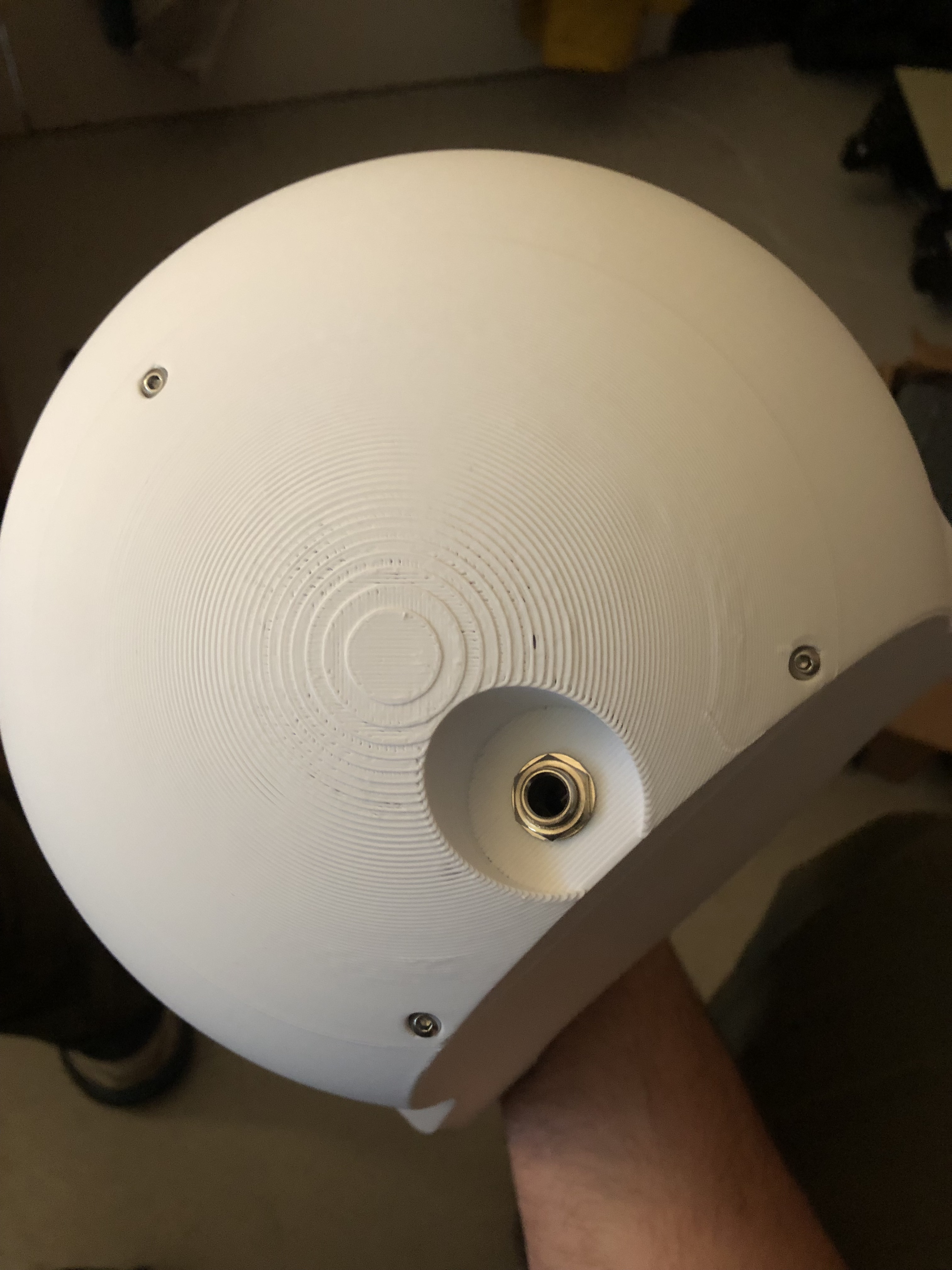
Install the 1/4" Female Jack: Insert the GLS Audio 1/4" female jack into the designated slot on the enclosure. Ensure it is securely mounted. if using a 2 way speaker, there are holes provided to attach the crossover board. You may need to print an adapter plate to attach the crossover board properly.
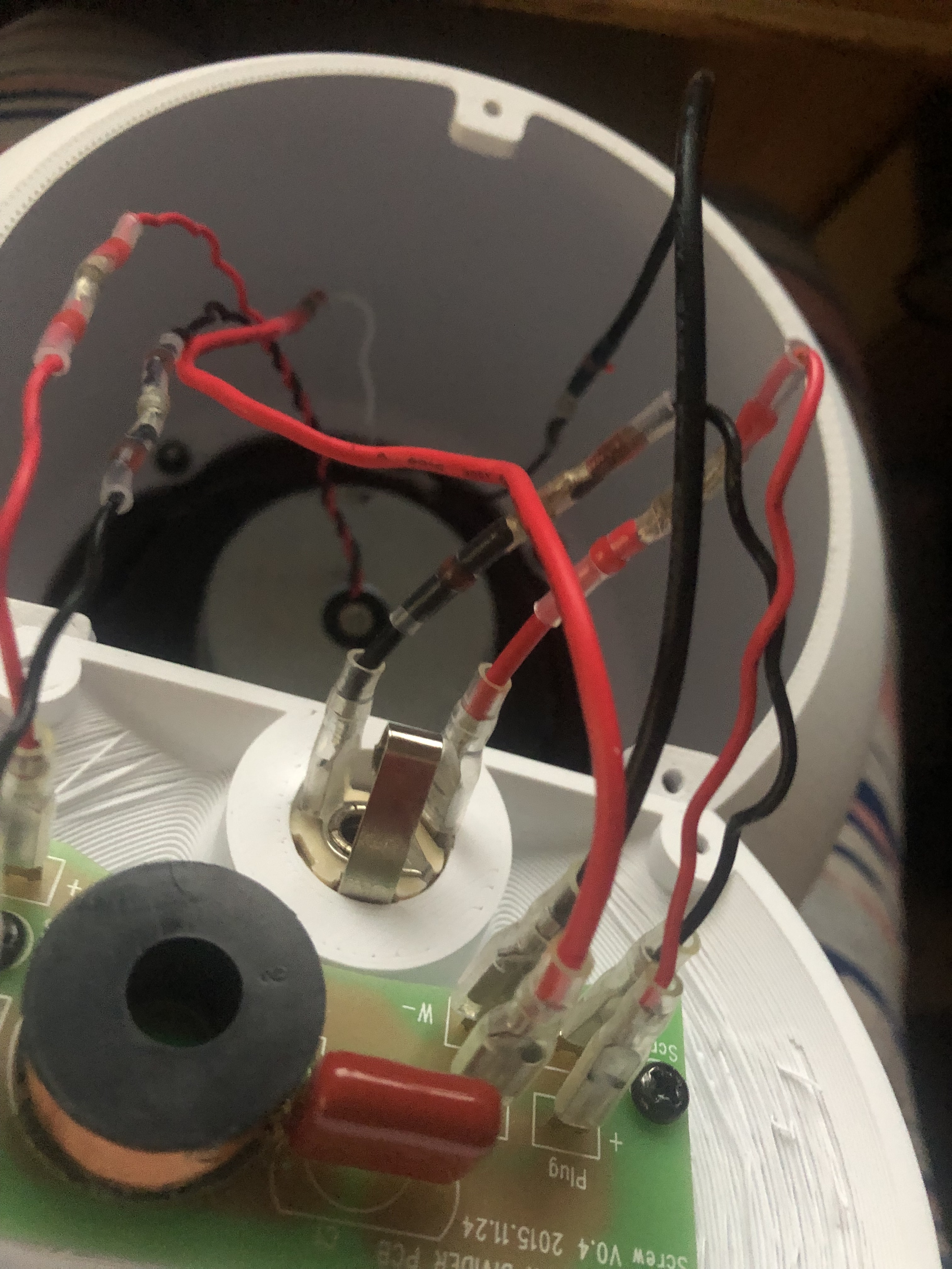
Connect Spade Crimp Terminals: Attach the 4.8mm spade crimp terminals to the speaker wires. Heat shrink and solder connectors may be used. Ensure the connections are insulated and secure. (Fig 3)
Mount the Speaker: Using M4 or M5 hardware, attach your 6.5-inch speaker to the enclosure. Use washers with nylon locking rings to prevent any loosening due to vibrations.
Attach the Speaker Back: Use M3 square nuts and 10mm M3 bolts to secure the back of the speaker to the enclosure.
Test the Setup: Connect your speaker cables (not instrument cables) to the 1/4" jacks and test the speaker to ensure everything is working correctly. If you are not looking to modify your amp to accept 1/4 in jack cables, then use my other upload that is FREE to create your own spring terminal to 1/4in jack adapters.
By following these instructions, you can create a professional and clean-looking speaker enclosure that enhances both the aesthetic and functionality of your audio setup.
Imbeded images
Fig 1. normal body print orientation

Fig 2. experimental body print orientation

Fig 3. crimp connector order

3D printing settings
High number of walls, such as 6 for a .4 nozzle or 4 for a .6 nozzle.
Low to zero infill, this design relies on wall strength
supports needed only for the grille and recommended for the back cover
Experimental body use tree supports and brim
:format(webp)/https://fbi.cults3d.com/uploaders/17092542/illustration-file/2c22d361-146b-4250-88be-5266b32ae707/IMG-5859.jpg)
/https://preview3d-images.cults3d.com/xcxbdvn5uk7u1wlxglircerdjbq7)
/https://preview3d-images.cults3d.com/8ji2esi0dhhcegik4i3b8xtp5xu0)
/https://preview3d-images.cults3d.com/c9l5p9ru0vmrq1ream6up4kirx4i)
/https://preview3d-images.cults3d.com/reyd0uh1dflt1fcl6xkh0jye1jsi)


:format(webp)/https://fbi.cults3d.com/uploaders/17092542/illustration-file/7799c2d9-5a30-4041-8879-9e3c1b2f5436/P1105783.jpg)
:format(webp)/https://fbi.cults3d.com/uploaders/17092542/illustration-file/7f30fb0f-608b-4ae5-8886-f24f647ac1b3/IMG_3117-MConverter.eu.jpg)
:still()/https://fbi.cults3d.com/uploaders/17092542/illustration-file/7bae6f6c-161b-4027-b356-10d580078d62/gifmaker_me-ezgif.com-crop.gif)
:format(webp)/https://fbi.cults3d.com/uploaders/17092542/illustration-file/53f16365-5852-4732-b8a3-b1d11abe53ed/IMG-0311.jpg)
:still()/https://fbi.cults3d.com/uploaders/17092542/illustration-file/0c5348f0-fc8d-4ad1-8270-bfaafbdc6718/ezgif.com-crop.gif)
:format(webp)/https://fbi.cults3d.com/uploaders/17092542/illustration-file/5091094a-2b4e-4e56-a481-2e2b1cb7914b/ezgif.com-animated-gif-maker-1.gif)
:format(webp)/https://fbi.cults3d.com/uploaders/17092542/illustration-file/ef912739-2ced-4e8d-9e61-2c1c335ad7d8/Ultimate-trellis.jpg)
:format(webp)/https://fbi.cults3d.com/uploaders/17092542/illustration-file/f1fdc81a-d285-43af-96c4-a205bab59b9b/unnamed-54.jpg)