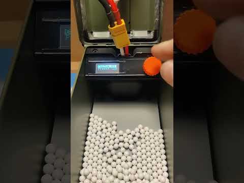
My screen freezes while I'm working and the engine keeps running. How can I solve this problem?
- 0 me gustas
:format(webp)/https://fbi.cults3d.com/uploaders/18372398/illustration-file/06720ce1-c245-468a-a5ec-08f85294ded6/IMG_20240323_150408.jpg)


/https://preview3d-images.cults3d.com/6jd08eq9iau6fxdxi2rf1ka3igwx)
/https://preview3d-images.cults3d.com/vzpivb0vabt1zqkt4c036rcmq1yj)
/https://preview3d-images.cults3d.com/wjg0bk101i9k899zowgcfe9hr681)
/https://preview3d-images.cults3d.com/l3tfci7jytq9b6127b7wgrqd13sw)
/https://preview3d-images.cults3d.com/7fl7v11k2sadcbq52wk5ez2wcqaa)
/https://preview3d-images.cults3d.com/r7srnkkvx5xykalj8bd0rr3ig5v5)
🔫 Los modelos 3D de pistolas o armas son objetos ficticios o juguetes y no tienen ninguna funcionalidad real como armas. Están destinados únicamente a fines de entretenimiento o decorativos. Para cualquier diseño contrario a nuestros T&Cs, por favor report.
| Licencia | |
|---|---|
| Usos | |
| Formato de diseño 3D |
9 archivos (PDF, STL, y ZIP) Cerrar
|
| Última actualización | |
| Fecha de publicación | |
| Número de diseño | 1875409 |


¿Te gustan Cults y quieres ayudarnos a continuar la aventura de forma independiente? Tenga en cuenta que somos un equipo pequeño de 4 personas, por lo que es muy sencillo apoyarnos para mantener la actividad y crear futuros desarrollos. Aquí hay 3 soluciones accesibles para todos:
Compartir y descargar en Cults3D garantiza que los diseños permanezcan en manos de la comunidad de creadores. Y no en las de los gigantes de la impresión 3D o del software que poseen las plataformas competidoras y que explotan los diseños para sus propios intereses comerciales.
Cults3D es un sitio independiente y autofinanciado que no rinde cuentas a ningún inversor o marca. Casi todos los ingresos del sitio se devuelven a los creadores de la plataforma*. El contenido publicado en el sitio sirve *únicamente a los intereses de sus autores** y no a los de las marcas de impresoras 3D que también desean controlar el mercado del modelismo 3D.


:format(webp)/https://fbi.cults3d.com/uploaders/18372398/illustration-file/c3035ed5-6a08-496a-a167-00d04bfddd34/filled-loader-basic-version.jpg)
:format(webp)/https://fbi.cults3d.com/uploaders/18372398/illustration-file/2f534735-8644-46c9-b472-7bb08e6d82dc/IMG_20240523_185931.jpg)
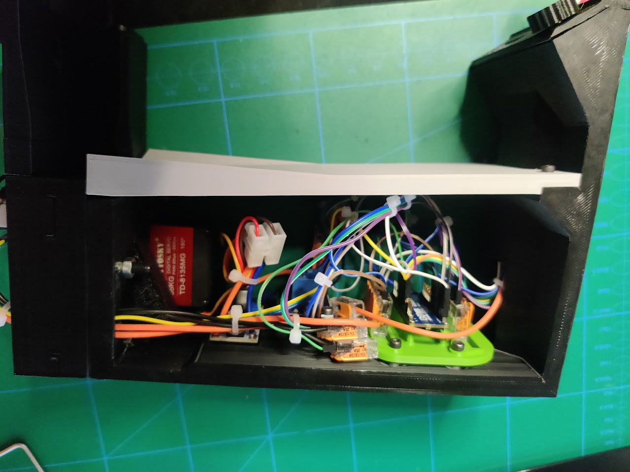
What I'm doing wrong, all the time gear is coming loose from motor