637 Scraper Builder's Guide
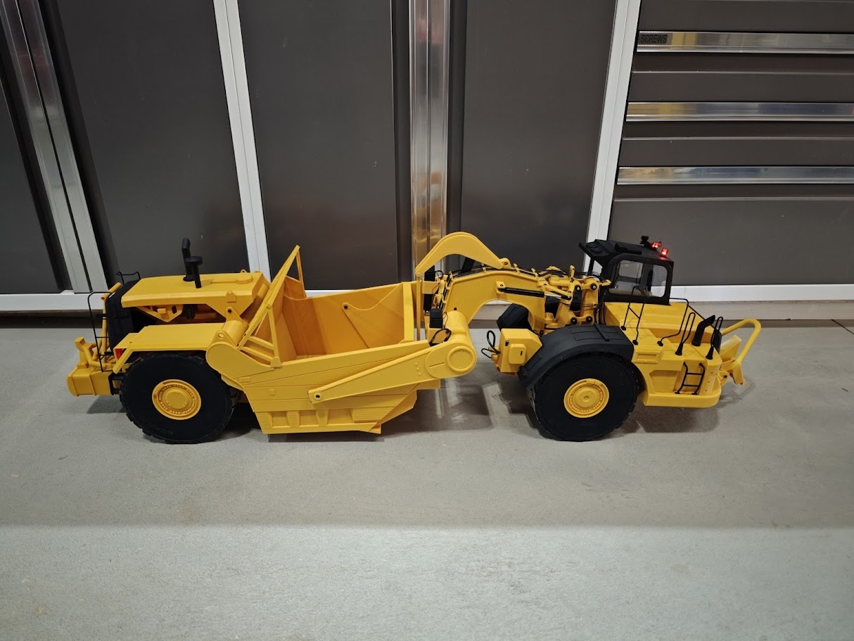
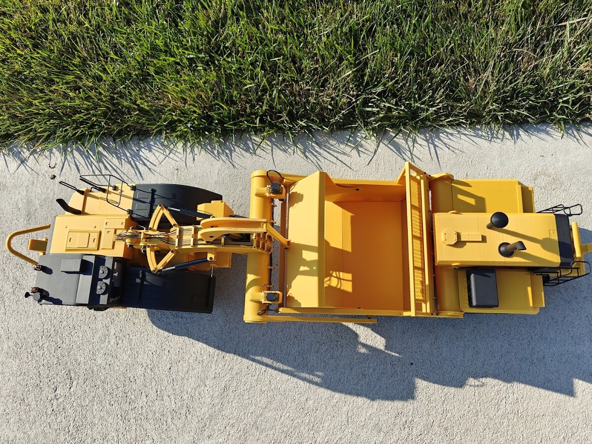
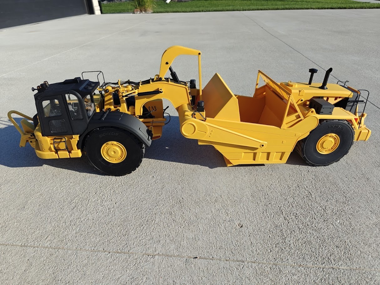
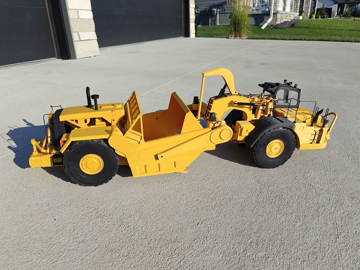
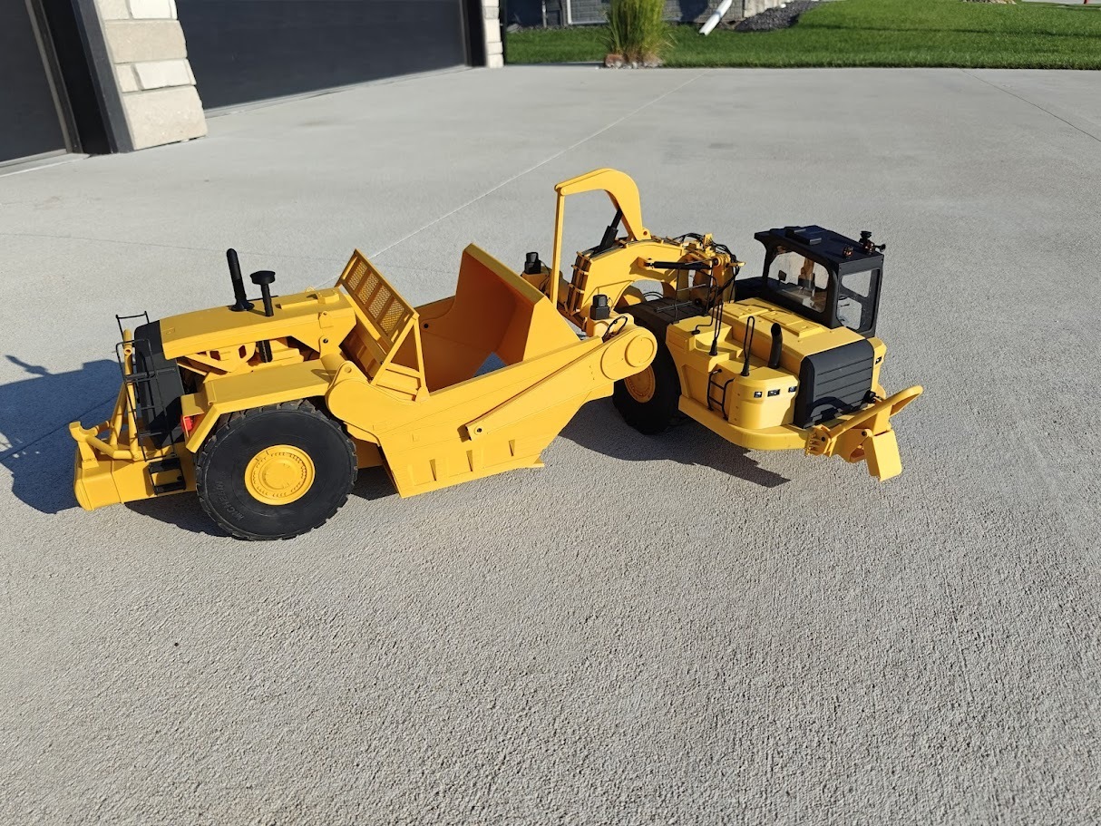
Welcome to the builder's guide for my DIY 1/14 scale Cat 637 scraper. This guide details my journey, the inspiration behind the project, and a brief overview of steps to build your own model. Please note that step by step set of instructions is NOT included!
About Me
I've been designing and 3D printing RC models for about four years, starting with 1/87 scale. In January 2025, I attended Cabin Fever in Pennsylvania, USA—an event I’d long admired through videos. The sight of hundreds of equipment models and trucks operating together was awe-inspiring, far exceeding what any video could convey. Motivated, I shifted to 1/14 scale modeling, beginning with a truck kit and expanding with factory-made imports and designs by creators like Burnie222 and Mushroom3D. When I decided to create my own 1/14 scale model, I wanted something distinctive, leading me to the all wheel drive 637 scraper.
Why the 637
Scrapers have always captivated me, but their complexity was daunting. The Cat 637, with its intricate prototype, presented a unique challenge. After considering other options, I kept returning to this iconic machine. The first obstacle was the tires—commercial “construction” tires max out at 142mm, but the 637 required 170mm. A conversation at Cabin Fever with Ralph Ford, who shared his method for casting urethane tires for his Tow Haul model, inspired me. I experimented with urethane casting, creating a six-piece resin-printed mold to produce scale-accurate tires.
Tire Design
The resulting tires, weighing approximately 1350 grams each, offer authentic appearance and excellent traction due to their weight. For builders hesitant about urethane casting, I’ve included a TPU-printable tire model as a simpler alternative. While casting requires patience and skill, it’s manageable with practice.
Designing the Model
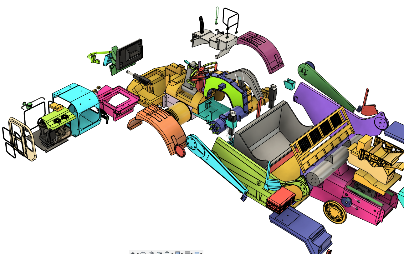
With the tires resolved, I used CAD to design the scraper, balancing accuracy with ease of printing and assembly. The goal was to minimize the need for specialized tools—no lathe or milling machine required, just a 3D printer, basic modeling tools, time, and a budget for components. For convenience, I’ve included Amazon links for parts (ideal for Western builders), though AliExpress offers similar components at potentially lower costs with longer shipping times.
Build Overview
The following are a few highlights from the build process, covering things like printing and assembling components to sourcing hardware. The project is designed to be accessible yet rewarding for dedicated modelers. I relied heavily on M3 hardware, with self-tapping or straight-thread M3 screws suitable for most parts. For the simulated steering/hydraulic ram linkages, use straight-threaded fasteners for better performance. I’ve linked M3 screw assortments in the BOM, which should cover nearly all needs with plenty left over. If you have a well-stocked workbench, you may already have most screws. I prefer button-head fasteners for exposed areas due to their polished look, but I haven’t specified exact screws, as most parts fit together intuitively. Photos and exploded drawings are included for clarity, and STL files are organized into logical folders with descriptive names, including “# X” for parts needing multiples.
Wiring and Electronics
I specified 30-gauge silicone wire for external feeders powering rear lights and actuators. Its flexibility and ease of soldering make it ideal, and the clamps are sized for it. Avoid stiffer PVC-insulated wire. For differential steering, each front wheel has its own brushed ESC, while the rear motors share a single ESC. You’ll need a computer radio to mix differential thrust for propulsion and steering. An 8-channel receiver is required for full functionality: two channels for front steering, one for rear propulsion, one for the apron actuator, one for elevation actuators, one for the ejector ram, and one for the cab-mounted beacon(s). I opted for always-on front and rear lights without a controller, but you can add one if desired.
Printing Specifications
Most parts fit on a 256x256mm bed (e.g., Bambu Carbon X1), except the bowl’s side plates, which require a 325x325mm build volume. For smaller printers, I’ve provided alternative side plates printable in two parts and glued together. For all of the structural or load-bearing parts, I used 3 perimeters and 45% infill for durability. Cosmetic parts like fenders and the hood used lower infill but maintained 3 perimeters. The front neck steering tangs and neck side plates were printed at 100% infill due to their small size and high stress. Adjust settings to your preference.
Bowl Floor and Cutting Edge
I included files for a two-part printed bowl floor and cutting edge, suitable for loose dirt or crumb rubber. Alternatively, a laser-cut file allows commissioning a 2.6mm steel floor and cutting edge for added durability and weight (cost ~$38 in the US). The steel version requires a shallow bend for the cutting edge’s kick, with two notches for alignment when bending.
Conclusion
I hope you find this build enjoyable and appreciate the effort to ensure parts align well for a smooth experience. Please share photos of your build here or on Facebook. Thank you for choosing my 637 scraper design—happy digging!
-Trevor
:format(webp)/https://fbi.cults3d.com/uploaders/13720297/illustration-file/ae31cc40-fb88-4630-9a9a-5be736fc2624/IMG20250727190126.jpg)
/https://preview3d-images.cults3d.com/ww80csgenkfxxwcqsm2pxjb1vnxr)
/https://preview3d-images.cults3d.com/xj93x7ui753tdb9amlhzgaj0a6v4)
/https://preview3d-images.cults3d.com/4f2rk4vn22xc7mdp7iwloy1e1aog)
/https://preview3d-images.cults3d.com/jgrbjbzfq7y0hhk985n8fg0f01ei)
/https://fbi.cults3d.com/uploads/user/avatar/13720297/Capital_customs_logo.png "CapitalCustoms")


:format(webp)/https://fbi.cults3d.com/uploaders/13720297/illustration-file/aab22dcb-ccf4-4ffd-9e5e-ae63edc1fd92/737-1.jpg)
:format(webp)/https://fbi.cults3d.com/uploaders/13720297/illustration-file/25f88348-c848-45ff-82e1-9765c0a96580/tail-car-7.jpg)
:format(webp)/https://fbi.cults3d.com/uploaders/13720297/illustration-file/66ed43ca-9ca7-448c-92fa-8aa2019ecd87/1000024635.jpg)
:format(webp)/https://fbi.cults3d.com/uploaders/13720297/illustration-file/1bb4fae8-d77a-4e0b-9203-c0937bd57824/Flatcar.jpg)
:format(webp)/https://fbi.cults3d.com/uploaders/13720297/illustration-file/73f2064a-3b9c-4b9b-8b65-71685b63f71e/IMG20250915130805.jpg)
:format(webp)/https://fbi.cults3d.com/uploaders/13720297/illustration-file/b15bb4a8-47ce-4743-afd5-4959ca93312c/Thumbnail.jpg)