Descrizione del modello 3D
I decided to dabble with Diesel Locos and pretty pleased with this N gauge model, specifically 1/148 scale.
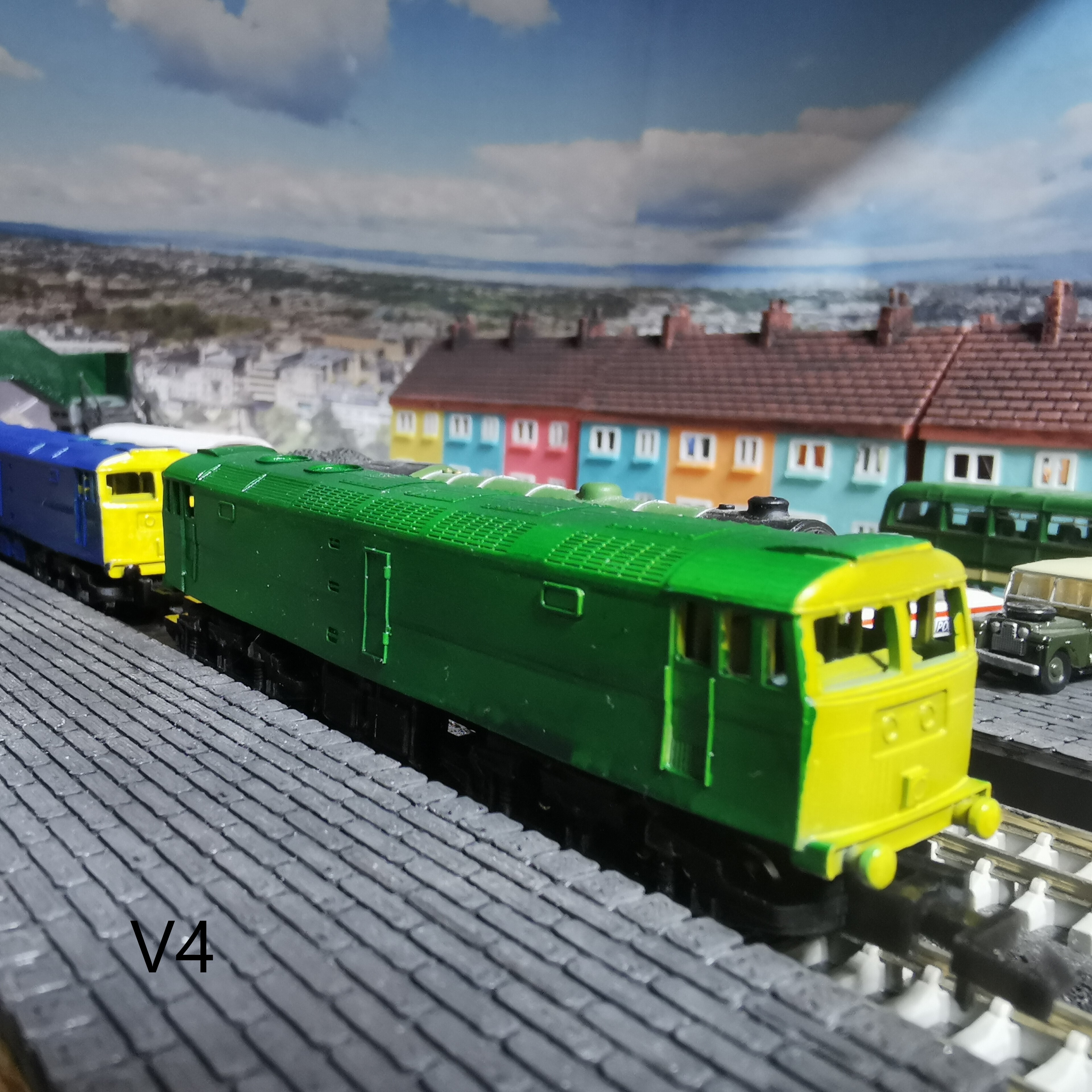
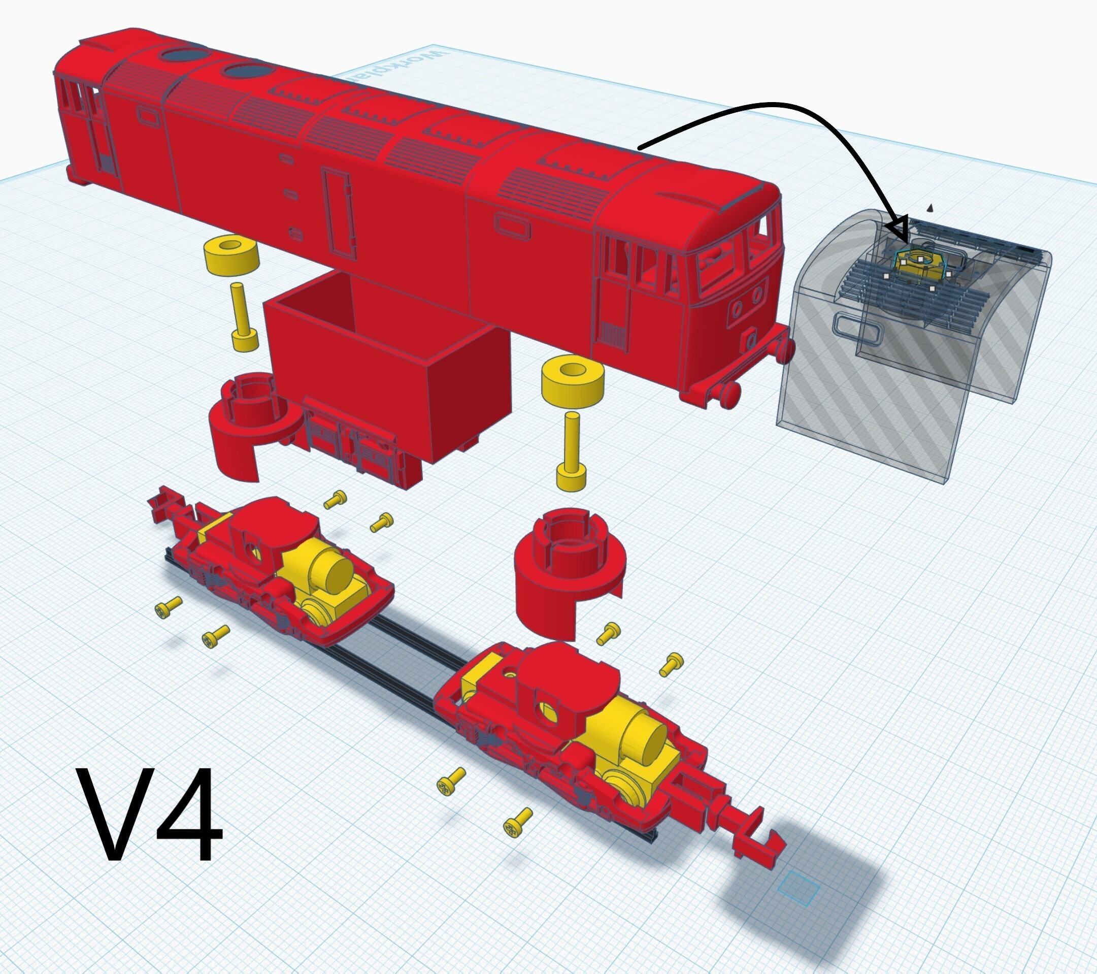
VERSION 4
Still using two stock power units and now made the model much simpler to print and assemble with fewer parts. I've added the STLs which have a V4 suffix. Part and assembly instructions are below in the setting and also included in txt file. Also see the new image for V3&4 assembly:-
Each power unit is secured with 4 screws each for better alignment.
The bogie top hats provide hinged movement for slopes and are easier to fit with a recessed edge. The bearing recess and assembly is now simpler to avoid damage.
The hopper is now designed for weights of your choice and simply clicks into position.
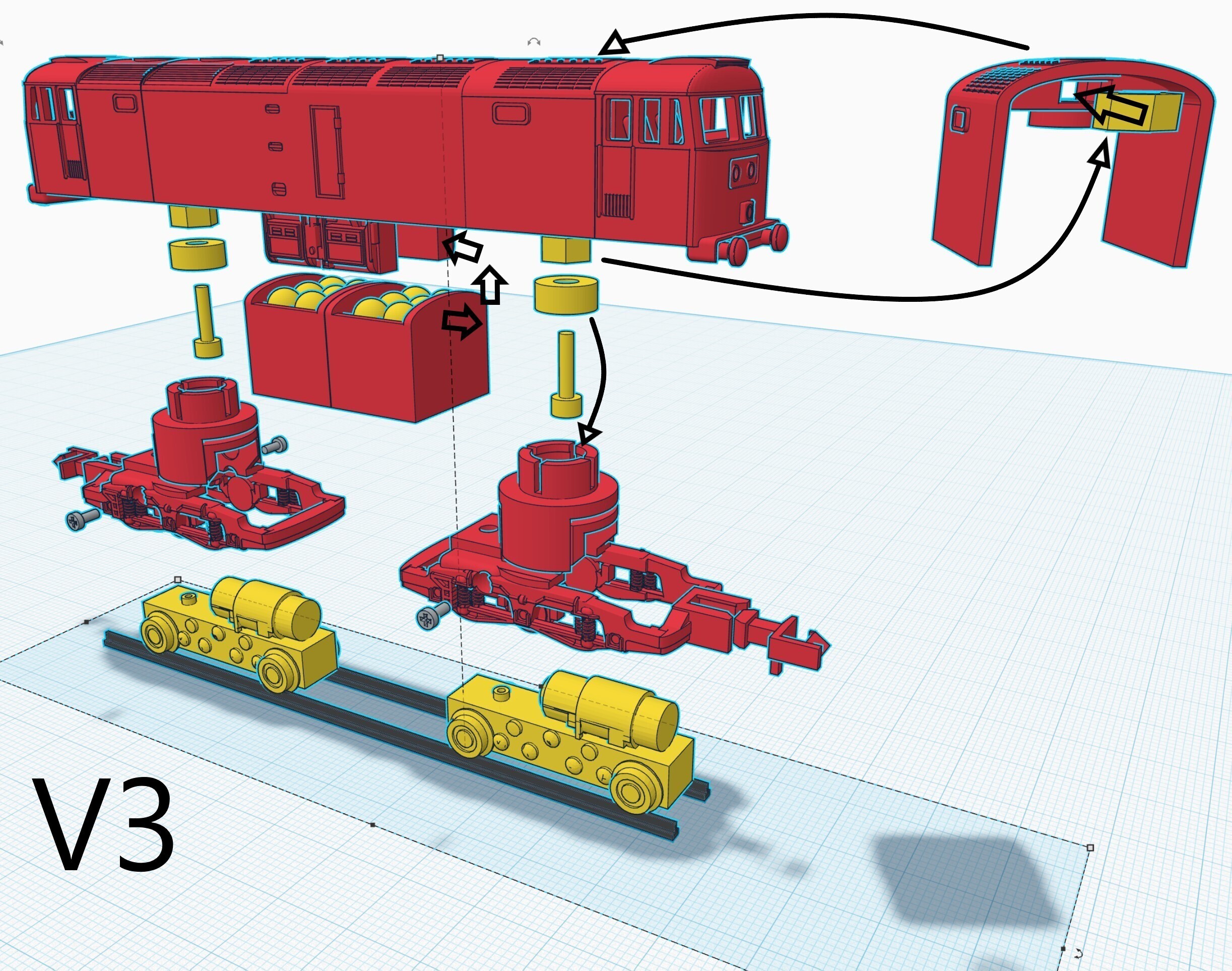
VERSION 3
Still using two stock power units and now made the model much simpler to print and assemble with fewer parts. I've added the STLs which have a V3 suffix. Part and assembly instructions are below in the setting and also included in txt file. Also see the new image for V3 assembly.
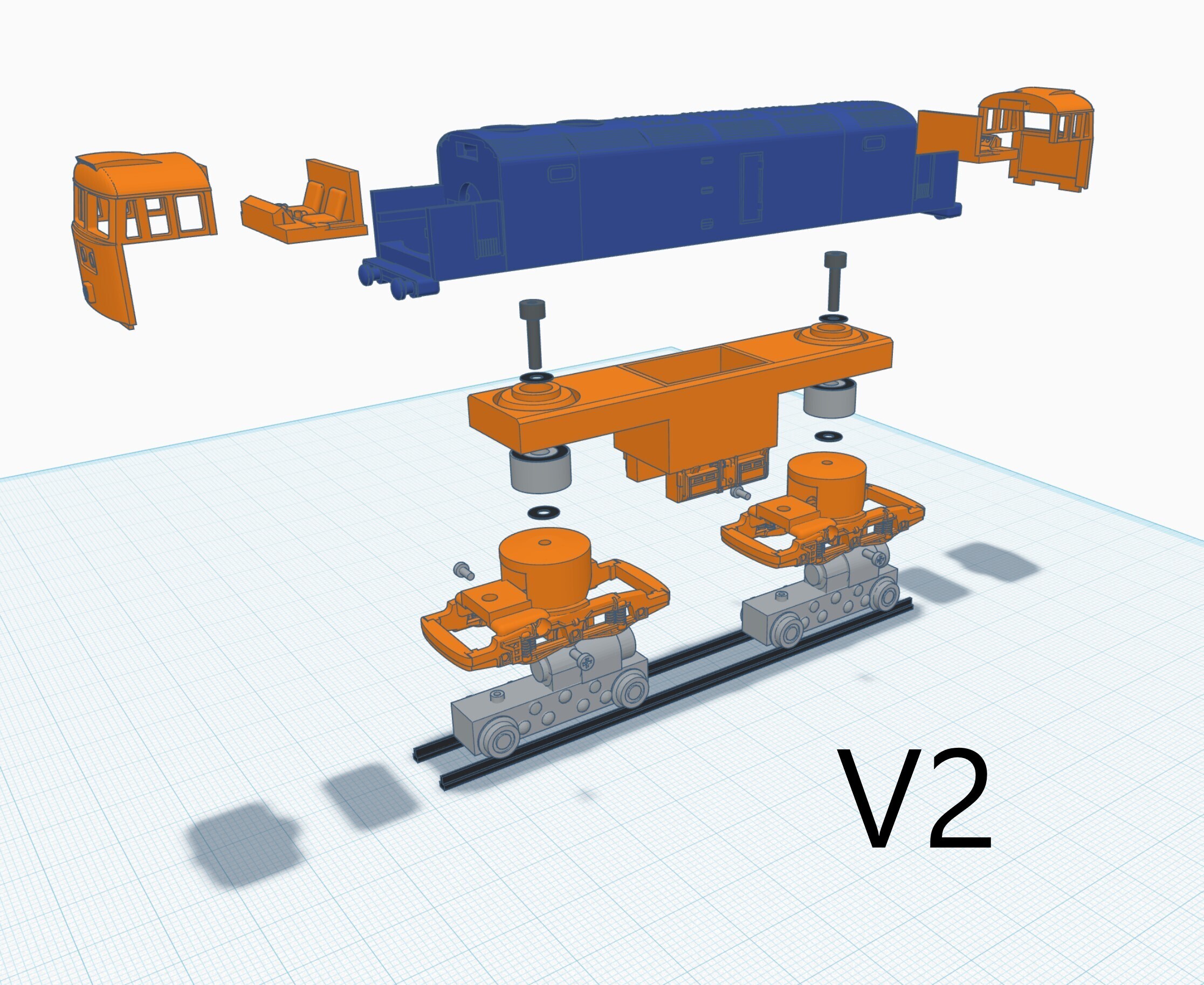
VERSION 2
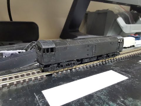
This version has been built and running, and now currently in the paint shop. Images to follow. I have added the v2 files - these have a v2 suffix in the file names. I have added a shopping list in the settings. Apart from the 2x Japanese motorised units the parts will cost a few cents. Also included a schematic/assembly for v2.
Added a complete body for v2. I'm hoping my masking and painting skills can do it justice!
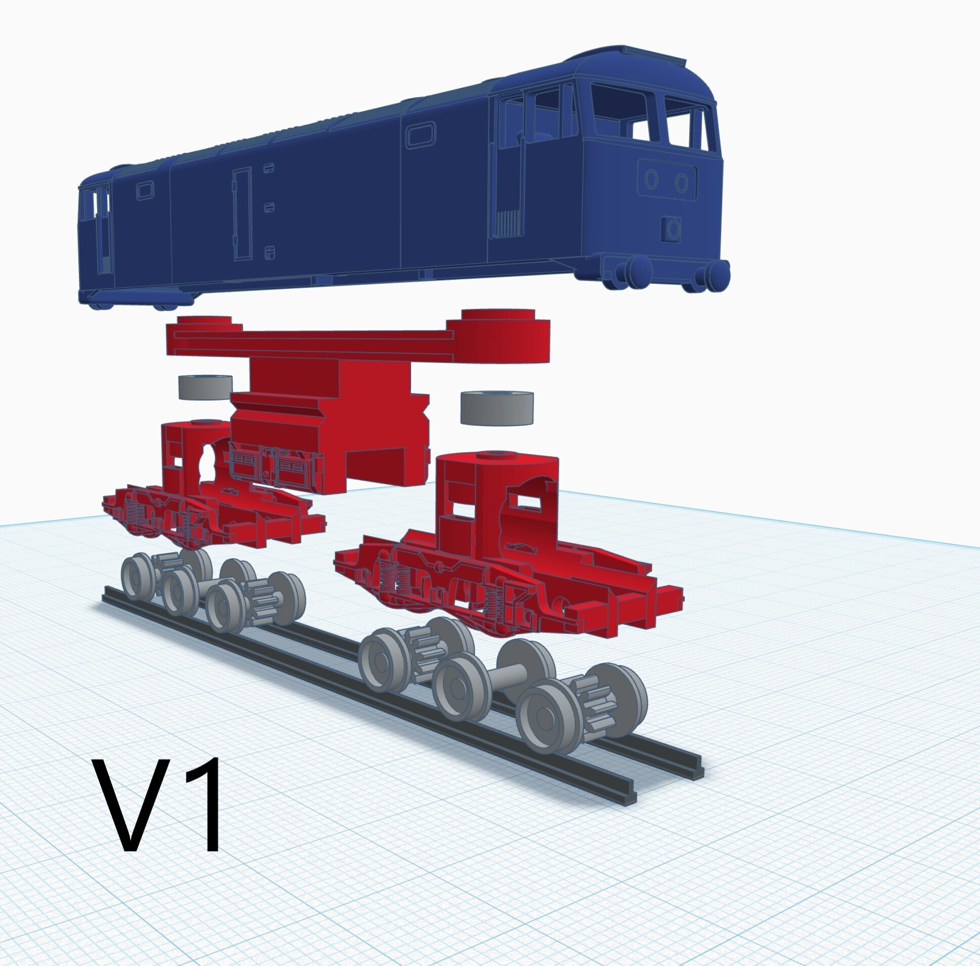
VERSION 1
I've now added all the parts required to produce a static model. Its a very intricate model and don't see it being printable in anything but resin. Obviously scaling up resin could be quite tricky given the capacity of an Elegoo.
The chassis has been designed to take dual shaft 8mm diam motor with worm gears on either end. I still have to figure how to mount the wheels. There is also the important aspect of the power pickup as well. Added image of motor onboard.
Impostazioni di stampa 3D
Please check out my profile to printing recommendations.
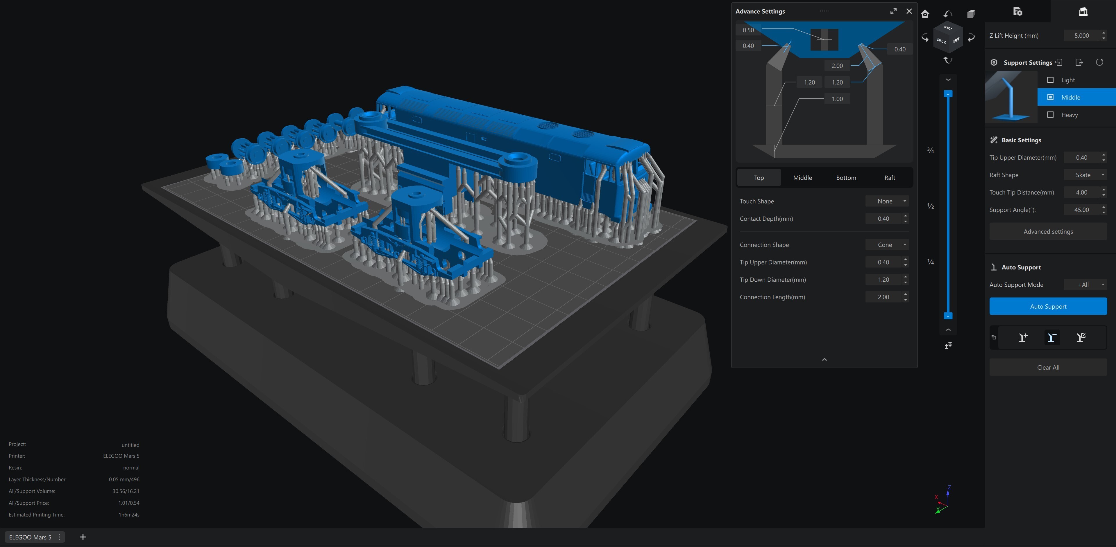
I've included a screenshot of Chitubox showing model layout for Elegoo Mars 5. I don't bother with angling anything as the model has no extensive sized planes and doesn't benefit. I don't mess with the defaults too much and just set supports to medium for a good print.
Print quantities are in the file names.
I used 2x No2 x 10mm csk screws for assembly. Its possible the whole thing could be assembled in slicer and printed all in one piece. Not something I have tried however.
If you want rotating bogies then swap out the printed 'bearing' for 2x bearings sized 7mm o/diam x 3mm i/diam x 3mm thick.
https://youtu.be/bIu79RZqxWc
Shopping list for v2 build:-
Screws - chassis to bogie
M2 x 8mm Hex (2x)
M2 Nut (2x)
M2 Washer (4x)
Screws - bogie to motor unit
M1.2 x 3mm (4x) - longer replacements
Bearing race
9x5x3mm diam x height x inside (x2)
Motor Unit
Plaza Japan Motorised Chassis TU-TMC100 (x2)
VERSION 3&4
I have printed on Elegoo Mars 5 using default light support. I used Elegoo black ABS-like resin with 20sec first layer to prevent over-adhesion. The black finish is ideal for bogies. Curing is minimal to avoid making the bogies too brittle.
V3/V4 Parts:-
Motor Unit - PlazaJapan Ref 4957265140339
(v3) Screws x4 - M1.4x3.5mm - Amazon Ref B0CLLGCYP1
(v4) Screws x8 - M1.4x3.5mm - Amazon Ref B0CLLGCYP1
Screws x2 - M2x8mm - Amazon Ref B0CPHM3RC1 (bearing)
Nuts x2 - M2 see ref above
Bearing - 3x7x3mm (id x od x thick) Amazon Ref B07FXXKZHG
Springs - 0.1mm wire x 1.4x10mm - AliExpress Ref 1005004657694818
(v3)Weights - Amazon Ref B09MNQP4MC
(v4)Now provided clip-in hopper for your choice of weight.
Assembly V3
Body:-
Insert the M2 nuts into the slots in top of body and attach the 2 bearings using the M2x8mm screws.
Bogies:-
Push fit the hinged top-hats onto the bogies. Make sure they move freely.
Motor Unit:-
The motor units only fit in one way into the bogies. Remove the screws in the motor unit that correspond with the screw holes in the bogie. Replace the removed screws with longer M1.4x3.5mm screws and secure the unit into the bogies.
Coupling:-
Push a spring onto each of the pins on each of the bogies. Now take the coupling hook and locate the other end of the spring into the recess in the hook. Carefully compress the spring and click the hook into place.
Weights:-
Fill the hoppers with steel balls then carefully push them into place into the body above the centre support.
Finally:-
The bogies are designed to push and click onto the bearing. Push gently with a little wiggle so that it clicks in place. This is why I avoid curing too much otherwise the resin can be too brittle for this step*. Make sure the coupling are facing outwards.
*redesigned in V4
Assembly V4
Hopper:-
Add weight to the hopper and fit into the slots of the body. I used a drop of iso-glue for a secure fit.
Body:-
Insert the M2 nuts into the slots in top of body ready for the bogies.
Bogies:-
Attach the tops hats to the bogies. These push on and should hinge just a little bit. Grab a M2x8mm screw and a washer and push through from underneath. Put the whole assembly on the end of your driver and screw into the M2 nut in the body. Make sure the coupling bracket is facing outwards.
Motor Unit:-
The motor units only fit in one way into the bogies. Remove the 4 screws in each motor unit that correspond with the screw holes in the bogie. Replace the removed screws with longer M1.4x3.5mm screws and secure the unit into the bogies. Make sure you don't catch the motor wires in the screw.
Coupling:-
Push a spring onto each of the pins on each of the bogies. Now take the coupling hook and locate the other end of the spring into the recess in the hook. Carefully compress the spring and click the hook into place.
:format(webp)/https://fbi.cults3d.com/uploaders/27405010/illustration-file/28311941-39e0-46ae-9643-44e1c7b1f09e/Class47LocoV4.jpg)
/https://preview3d-images.cults3d.com/rl097rot0n4exaa8lszl8os4vqfv)
/https://preview3d-images.cults3d.com/0evt4t03yce0zlboxnl0lacmiv4f)
/https://preview3d-images.cults3d.com/fcq9cynw0xo7dpxqw0oxe7kkw4mt)
/https://preview3d-images.cults3d.com/cad36vt3c3bulzdc1g6y1c2n96z6)
/https://preview3d-images.cults3d.com/va6r86xk3afgs44n7shaavrank07)
/https://preview3d-images.cults3d.com/yzypm13ppvvzqsdckhwe7i2c4uay)
/https://preview3d-images.cults3d.com/kfp7ma675zv6ng1vvbvzvximljdp)
/https://preview3d-images.cults3d.com/ng3ohpu3lmza8mfgghp0obi2s9lp)
/https://preview3d-images.cults3d.com/uxji9jxzf0rjsl9nw81cp9s21qgj)
/https://preview3d-images.cults3d.com/awkhsrqr3p4qccb3abx80auk8ru8)
/https://preview3d-images.cults3d.com/2ohj09ilbqu2nr2u4fzsrns0uriv)
/https://preview3d-images.cults3d.com/uklwt1lhqgp535e1zcra8wivr5bt)
/https://preview3d-images.cults3d.com/gj5csvb7ra39p67umzatckq1n7ca)
/https://preview3d-images.cults3d.com/l43zxy049mynxn0a6j3tiy6gsomb)
/https://preview3d-images.cults3d.com/z6bkcuel7vvy8tdgnngb089ugb03)
/https://preview3d-images.cults3d.com/s06ifkbasn7e9fbedzsrziamnhry)
/https://preview3d-images.cults3d.com/84wjf2jtth3g7rzd1rlwrs2xbvbl)
/https://preview3d-images.cults3d.com/elbmbea5ya910fx7rqx8afn2a2tt)
/https://preview3d-images.cults3d.com/r79gavlim75v0k6r98ph3psr934n)
/https://preview3d-images.cults3d.com/j5qomrfgibbqr1o272bs9uoxu2z9)
/https://preview3d-images.cults3d.com/rlevx77e9z79sh80qx2vk6in8ojy)


/https://preview3d-images.cults3d.com/ibx7lr5gjegjitt8wvqazrvpjmfp)
/https://preview3d-images.cults3d.com/kb6q17qr4pdk9bru0d3fwfi8cbm6)
/https://preview3d-images.cults3d.com/tb6c51ss8hlq663g1aio9movd8v9)
/https://preview3d-images.cults3d.com/fihriuifytexb22lfdppld7e06xg)
/https://preview3d-images.cults3d.com/bjs5nw2n6rc05w5038sttklc6wqi)
/https://preview3d-images.cults3d.com/dmk27oak7apm9s3jhwxsfo1rrgp6)
/https://preview3d-images.cults3d.com/9jndwbak7x441whr8ih0r9qjfoin)
/https://preview3d-images.cults3d.com/li2sst4plyauahk44ehbdfyvp4c3)
/https://preview3d-images.cults3d.com/6k4xnm9ucerdqem9w2lf50gl8ehj)
/https://preview3d-images.cults3d.com/wku796anoff4tesjyttx7is6h6sv)
/https://preview3d-images.cults3d.com/iohgc9pkr2yh2djbr7vnciw82gz5)
/https://preview3d-images.cults3d.com/dsi7y2fp1lhh26eu8jkistcgwki5)
/https://preview3d-images.cults3d.com/h5j4cdml2xjtl07v5dw5s3o5trhv)
/https://preview3d-images.cults3d.com/9qc6mh14o5fboy6z9x56zfr2aq0s)
/https://preview3d-images.cults3d.com/4kj0d55yxj6gkninempg0w6vntiz)
/https://preview3d-images.cults3d.com/8l13mymgk6380voht2umt66o2jzs)
/https://preview3d-images.cults3d.com/s1yfk64is8uzw359il9y4bfe1mbf)
/https://preview3d-images.cults3d.com/fpllzehxktn0zs3r7dzrgo65uic5)
/https://preview3d-images.cults3d.com/1femclaav9wevrge2m0euabh1i2z)
/https://preview3d-images.cults3d.com/z3rizgug7vtog11iiglo6rnh6y2o)
/https://preview3d-images.cults3d.com/yaj0cpbvwbqaqehuwjymwl9rwsd0)


:format(webp)/https://fbi.cults3d.com/uploaders/27405010/illustration-file/d4e1bb2c-2476-498d-9104-8db565a10519/IMG_20230307_195142.jpg)
:format(webp)/https://fbi.cults3d.com/uploaders/27405010/illustration-file/4abbbb6b-32e3-40d7-ab24-4edf703ad445/IMG_20230414_211715.jpg)
:format(webp)/https://fbi.cults3d.com/uploaders/27405010/illustration-file/805e68f1-3880-456f-b111-16d1307cdf36/St-Peters-Image01.jpg)
:format(webp)/https://fbi.cults3d.com/uploaders/27405010/illustration-file/19a3878d-c285-44fb-a639-17d468e5f260/IMG_20230416_190255.jpg)
:format(webp)/https://fbi.cults3d.com/uploaders/27405010/illustration-file/54a47299-d878-4562-ba6b-9dcfcccf15d6/IMG_20230513_170923.jpg)
:format(webp)/https://fbi.cults3d.com/uploaders/27405010/illustration-file/1599dd8d-9990-4bc4-a229-c20c7bd09b2b/IMG_20230422_201258.jpg)
:format(webp)/https://fbi.cults3d.com/uploaders/27405010/illustration-file/0c443ae2-4907-4f14-a812-ee7136acbcde/IMG_20230422_163027.jpg)
:format(webp)/https://fbi.cults3d.com/uploaders/27405010/illustration-file/7956db07-1ca9-4974-b208-8508e4681382/IMG_20220403_151142.jpg)